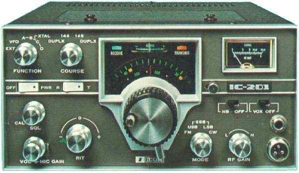
ICOM IC-201
I'm among those guys, owning an ancient ICOM transceiver model IC-201. Since this is a good, analogue all mode transceiver for 144-146Mhz there might be some interest to set-up a database with additional information. There are some known problems with this transceiver and I like to investigate if there is a base for collecting this information, since ICOM was not able to help me and others out.
I'll appreciate a response of everybody owning this IC-201 and have some interesting solutions for other users.
Known users:
| IZ0GYQ - Enrico | IK8XFR - Guiseppe | DL3EAZ - Kai | PA5TIG - Johan |
| PA0JCA - Sjaak | IW3ERC - Sergio | IZ5IUY - Franco | EA3GNS - David |
| DF1EQ - Jürgen | EA3BTZ - Enric | DK7YG - Gebhard | ES5AKC - Mart |
| SM1HOW - Lars | PE1PWF - Edwin | PA3BCI - Daan | DL7MAJ - Stefan |
| DK1NL - Marcel | G4FUF - Keith | ON3AD - Jeffrey | F4HOR - Gerard |
| PA3JVC - Johan | DJ1AUS - Alexander | DB5YB - Jürgen | DK7CB - Franz |
| PA0JGF - Jan | DK5EQ - Willy | PA2WLE - Wilbert | RV3APM -Serge |
December 2013 - I bought 2 VFO SDR kits to replace the analog VFO for a nice Digital Display. info: www.sdr-kits.net
December 2014 - One of the IC-201's has been converted to a DIGI-201 and is almost completed. see photo galery
February 2015 - A NEW IC-201 is born!
October 2015 - Another Digi IC-201 is born in Munich at Stefan DL7MAJ
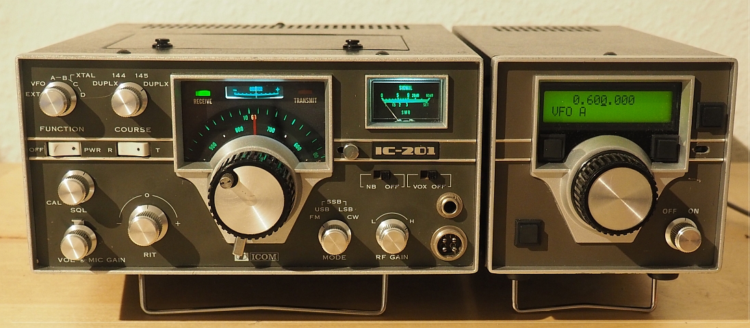 |
Picture on the left is the modified VFO VF221 using SDR
kits. Really a state of the art job done by Stefan, DL7MAJ.
Stefan also rewrote the alignment procedure for our IC-201. Download the pdf document here: Alignment-IC201 It is worth visiting Stefan's website for more news to come:
|
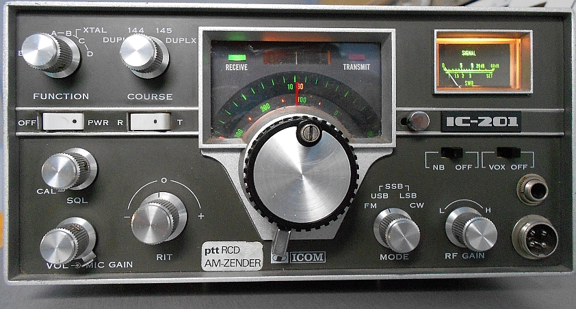
standard VFO |
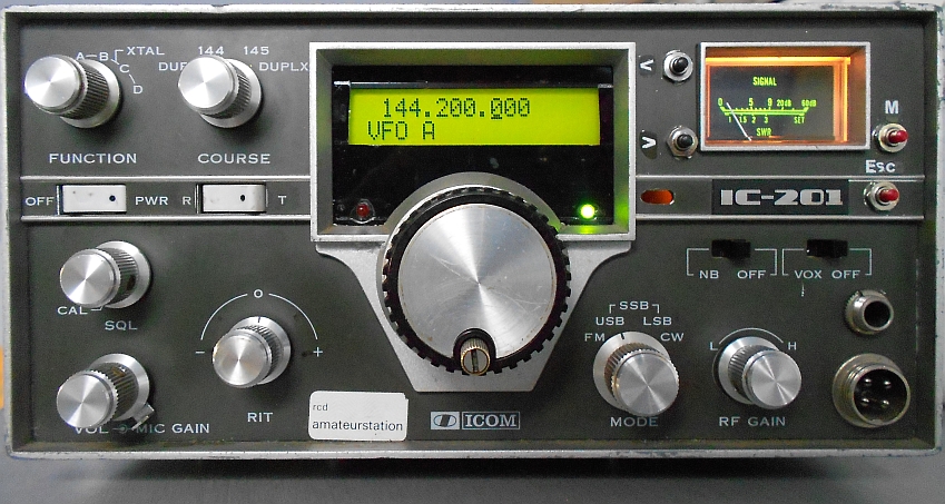
Digital VFO -> info: www.sdr-kits.net |
Please contact me at: info@pa0ply.nl
| Problem | Call | Date | Solution |
| Bad connection to centre PCB | PA0PLY | 14 Aug 2006 | Remove all feedtroughpins and
resolder feedtrough properly
(See picture) |
| Problem to go from RX to TX mode | IK8XFR | 4 May 2010 | Cold solder points on AF-board |
| Mechanical problem with VFO | PA0PLY | 26 Mar 2004 | Not yet solved |
| Modification | Board Ident | Date | Solution | ||||||
| Loud plop during CW-operation | U69-1 | 14 April 2004 |
|
||||||
| Very strong CW-monitor sound | U69-2 | 14 April 2004 | Change R64 into 330kOhm | ||||||
| Provide Low Power RF output (abt. 300mW)-simple solution | U74-1 | 14 April 2004 | Shortcircuit R20 with switch | ||||||
| Low Power output, modifying PA section to maintain S-meter function | TX-PA | 27 October 2006 | Remove entire PA section and remove driver transistor | ||||||
| Enlarge freq. range to cover 143.600MHz | Frontpanel | Change wiring of Course switch S3
as follows:
Relocate yellow wire from S3-1/pos1 to S3-2/pos1 Remove brown wire from S3-3/pos1 See also picture section |
|||||||
| CW operation in SSB - mode | U69-2 | 27 October 2006 | No need to switch to CW for sending small CW messages in SSB-mode. |