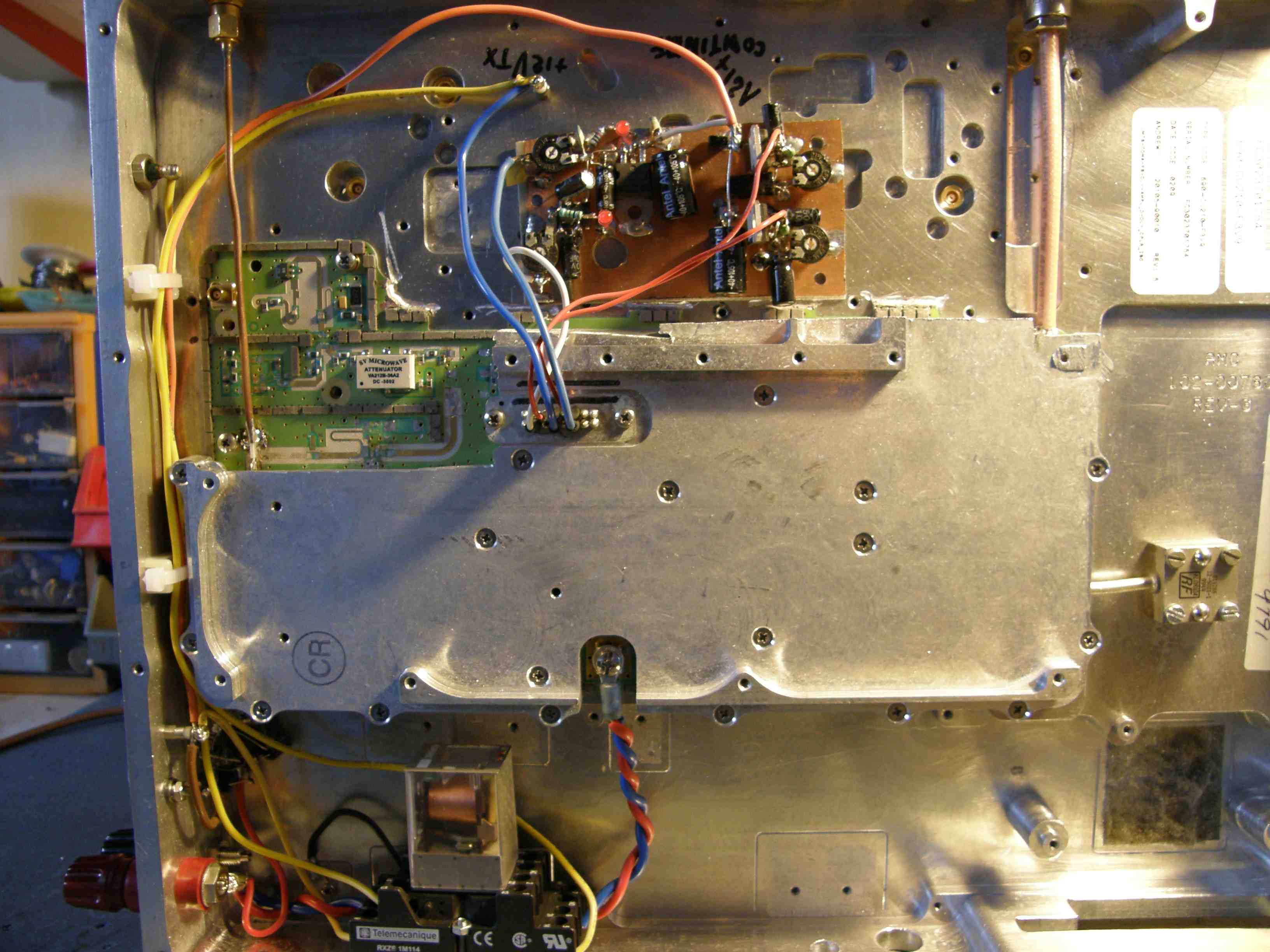
HPA Section of ANDREWS ex- UMTS PCB |
In this section I describe the modification of the HPA, High Power Section of an ANDREWS UMTS unit to be used for 2320Mhz.
This section contains following components:
|
Component |
Vds |
Vgs |
Gain |
Pout |
|
U17 |
15Vdc |
-5Vdc |
12.5dB |
32dBm |
|
FLL57 |
15Vdc |
-5Vdc |
11.5dB |
36dBm |
|
MRF 21045 |
28Vdc |
+5Vdc |
15dB |
45Watt |
| MRF 21125 (2x par) | 28Vdc | +5Vdc | 13dB | 125Watt (2x) |
Using the multipole connector the various connections can be found here: Connections
:First test of this section of the board was on the DC levels and currents.
Following settings were found to be more or less optimum for the time being:
Ir = 400mA ( U17 & FLL57)
Ir= 500mA ( MRF21045 )
Ir= 500mA ( MRF21125 )
I first modified the input section: U17-FLL57 and got 1.5Watt out with 7mWatt drive.
After this I used the entire set-up and applied 24Vdc on the MRF's
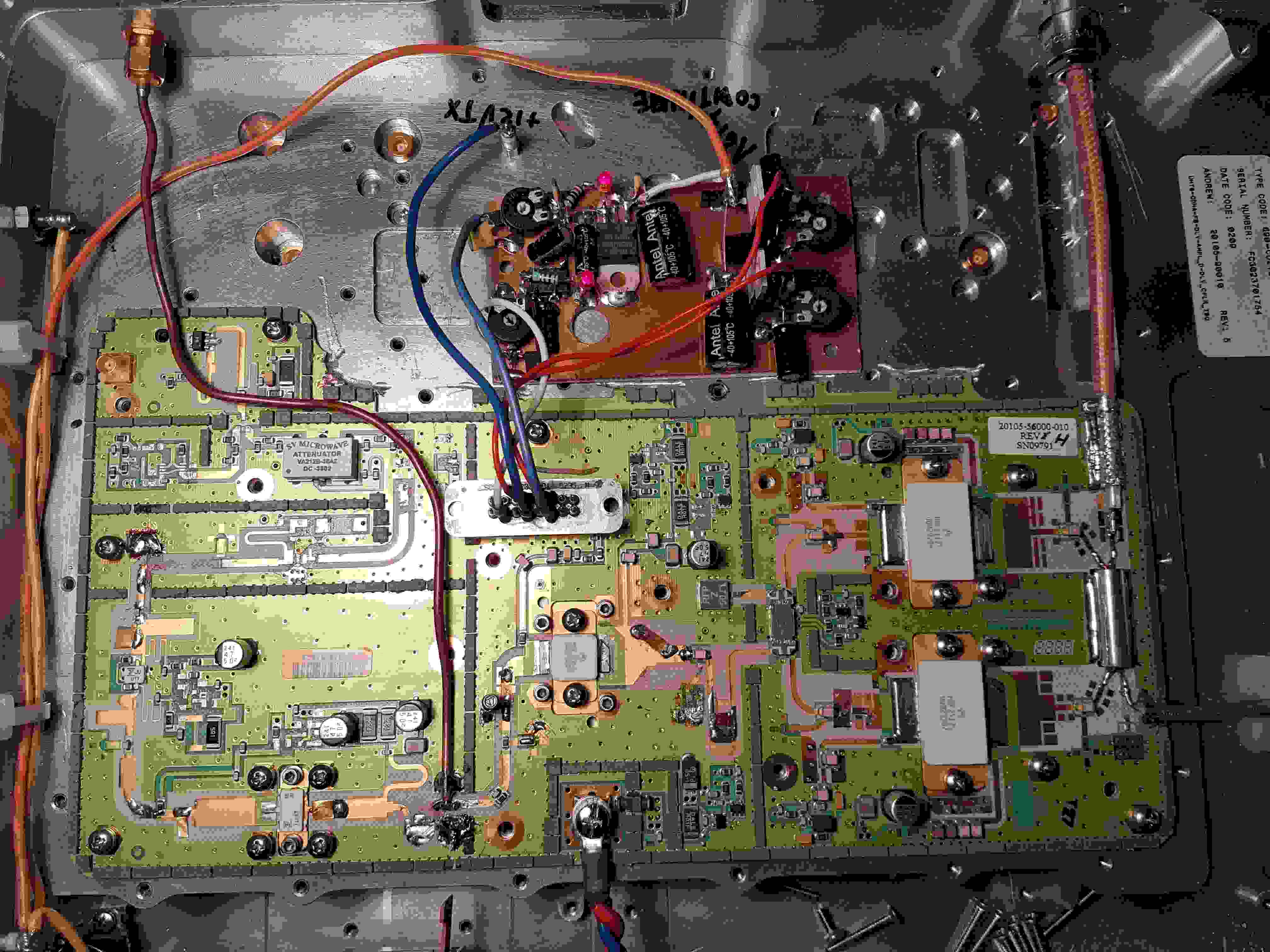
The final modifications are shown in below picture. Note: I consider to further optimize the final stage as not much was done on this.
Currently 28Vdc applied with the over on: >150watt out.
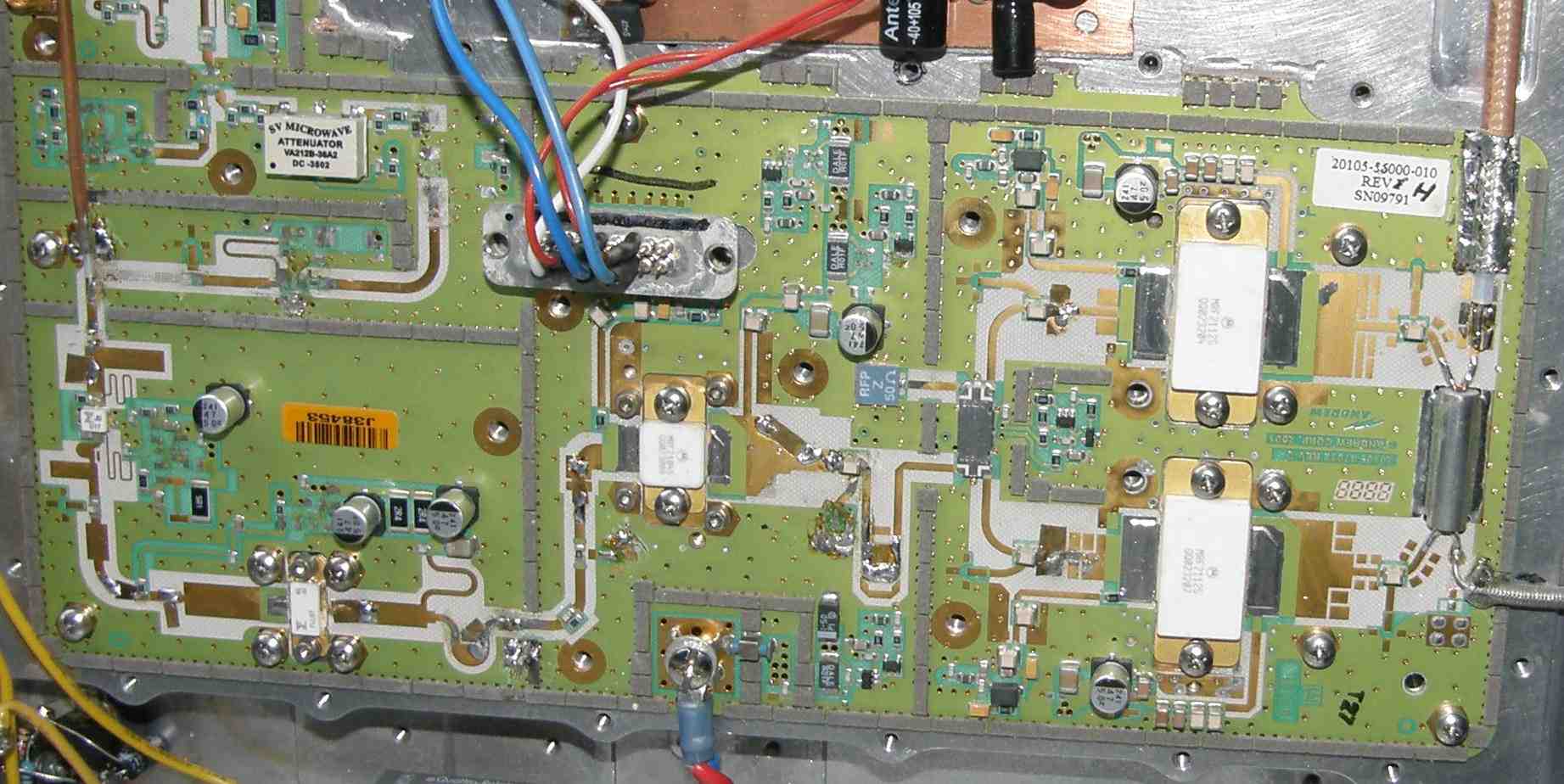
Checked the MRF 21045 and MRF21125 section and have 23dB gain.
The final HPA modified PCB: Good for >150Watt RF output